Where are the +/- power supply connections of an IC? (Vcc, Vdd, Vss or GND...)
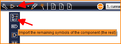
The power connections of a device having several gates mostly are treated separately. Those Power connections are not automatically "inserted next" but "as rest". There is an extra menu item and also an individual button for pending (not yet inserted) gates:
(Image 1: Little white extension besides the component database button
And in the sidebar there is a dedicated link:
(Image 2: Sidebar showing a link for "Rests of components")
Now a dialog opens showing various "rests" of components. In the U5 case there is only gate "a" inserted.
(Image 3: U5 has some rests to be imported)
Gates b, c and d come automatically with the next clicks to the schematic, p is a remainder, a rest. It represents the power pins and needs to be imported by separate action.
This is how U5p looks like:
Image 4: The power pins of U5, imported as rest.
In most cases it gets placed together with the power symbols of other components bottom right in the schematic in order to connect it to +5V and GND. The handle cross is just a help for edition and will not get printed. The suffix "p" will be suppressed if the text in the symbol showsText-function "Component name" instead of "Symbol name".
 (Image 1: Little white extension besides the component database button
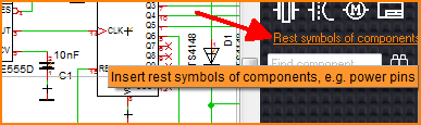 (Image 2: Sidebar showing a link for "Rests of components")
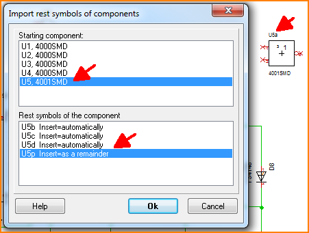 (Image 3: U5 has some rests to be imported)
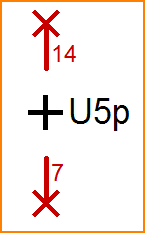 Image 4: The power pins of U5, imported as rest.