in the Demo project "dice" there is a push button implemented. It is open for a period of time, then closed and then open again: (Figure 1: Push button in simulation) If you want to assign a simulation model to such a push button, you need to create a new subcircuit, which - as a circuit - has the same content as the pushbutton in the dice project. Click buttons [Simulation values] and [Select]]. (Figure 2: Select a device subcircuit)
(Figure 3: Establish a new subcircuit)
(Figure 4 : Define subcircuit)
You must enter nodes 1 and 2 for a push button and copy the circuit and, if necessary, also the parameters as text blocks from the push button of the Dice project. The push button is open for 50 milliseconds, then it closes for 20 milliseconds and then it is open again for a very long time. You then need to do some pin mapping, for example the SMD push button in Dice has 4 pins, maybe yours only has 2.
U1 in the text of the circuit is a digital gate with a stimulator function, this is where the line sequence is set. U1 is connected to the generic digital voltages ($G_DPWR and $G_DGND) and to an internal node CTRL. Resistor R1 (=100k) and capacitor C1 (10nF) smooth the otherwise "angular" switching process to the further internal node C. Current source B1 is a B-source (arbitrary behavioural voltage or current source) whose internal resistance is controlled by the voltage at the internal node C. This B-source finally hangs between the actual switching contacts 1 and 2. 100Meg is the resistance of the button when the contact is open.
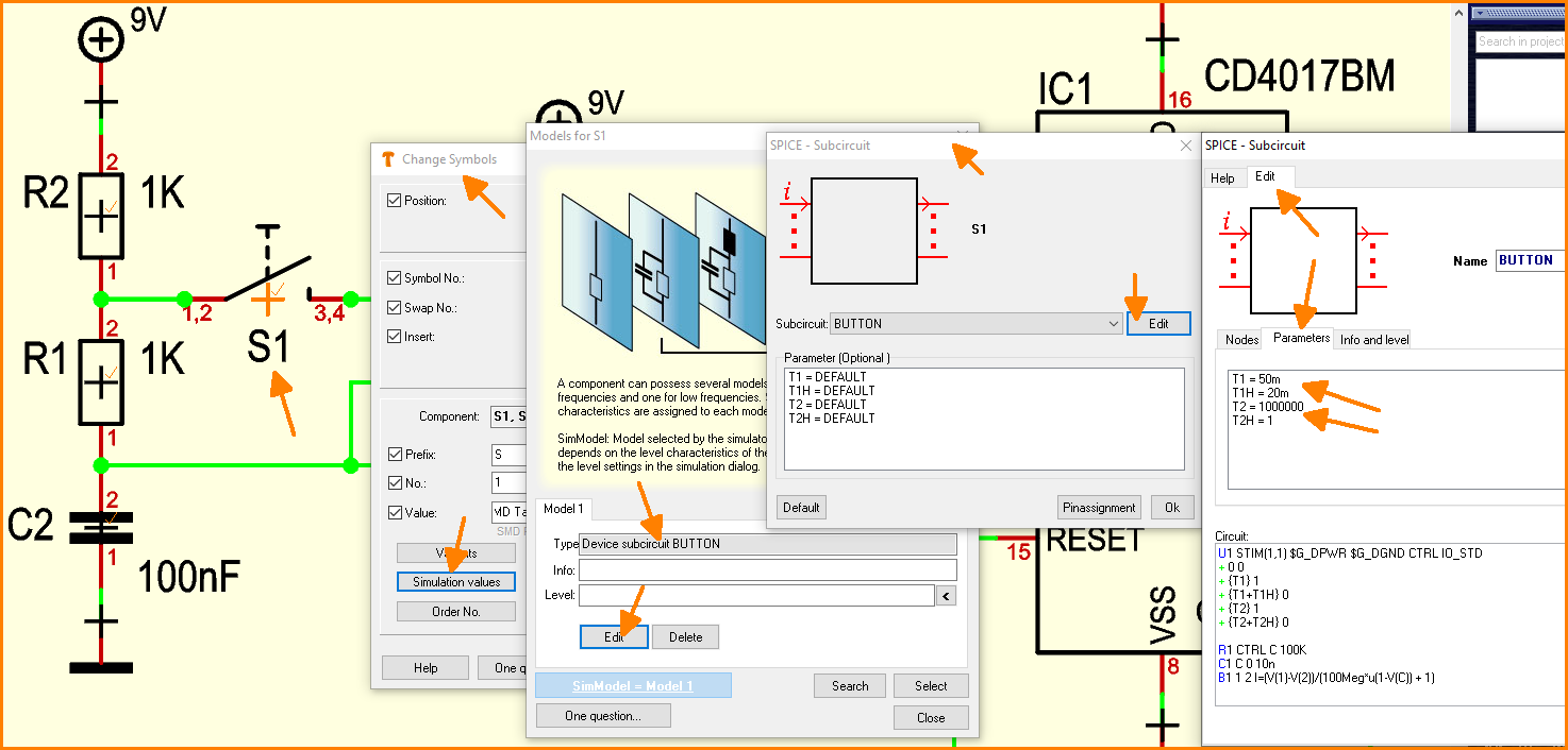 (Figure 1: Push button in simulation)
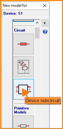 (Figure 2: Select a device subcircuit)
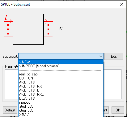 (Figure 3: Establish a new subcircuit)
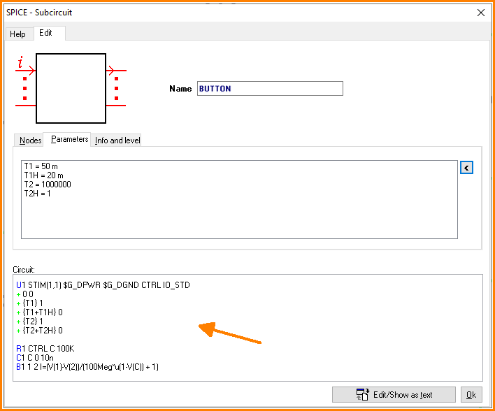 (Figure 4 : Define subcircuit)