Theme: PCB outline, shape of the board, copper layers, layers
How can I create a Rigid-Flex board?
Mainly you need 2 outline layers for this: One layer with the multiple outlines of the individual rigid boards and one layer for the entire construct, i.e. for the one common overall outline that also includes the flexible areas.
For the individual rigid boards, use the normal board outline, e.g. on layer 23, as usual. For the overall outline, you must create a new layer function in the big layer dialog, for example "Outline-Rigid-Flex" for layer 28:
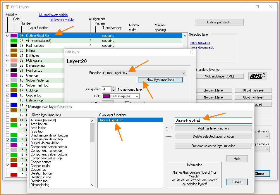 (Fig. 1: Create your own layer function).
Then draw the outline of the overall design onto this layer 28. Talk to your PCB manufacturer about how many copper layers should be available in total, and which ones can only be used in the rigid areas and which ones can also be used in the flexible area. There are a lot of other design rules from the PCB manufacturer to go along with this. Here is an example:
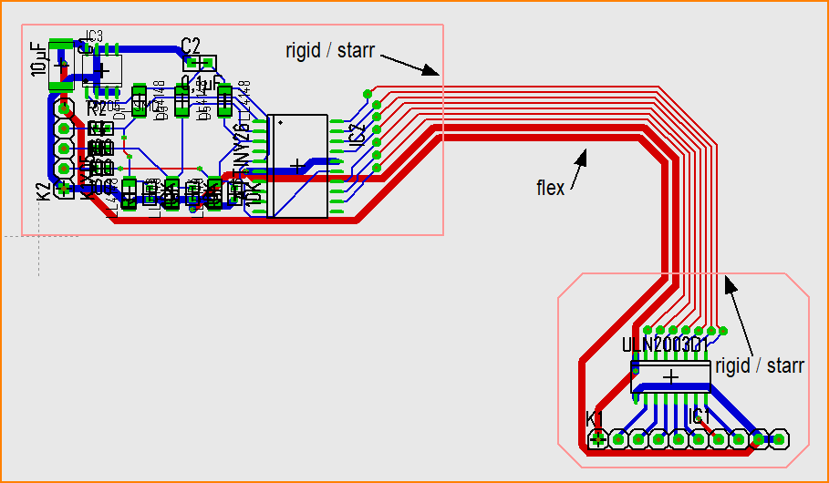 (Fig. 2: Two outlines of the rigid areas, light red, layer 23)
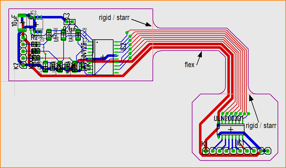 (Fig. 3: One common outline for all areas, rigid plus flexible, purple, layer 28)