One question...

Theme: PCB outline, shape of the board, copper layers, layers

How do I create a breakout inside my board?
The outline of the board is nothing more than a closed polyline around the outside of the board. This line should be drawn on the "PCB outline" layer which by default is layer 23. So just draw another closed polyline inside the outline on layer 23. This inner line represents the breakout.

Circular arcs (tori) or spline curves can also be used. It is important that the end of a line is exactly at the beginning of the next line. To check this, you can press the [#] (=hash) key to check the ends of the lines. The exact cutting edge of the board is determined by the middle of the lines, so the width of the line itself doesn't matter.

1 
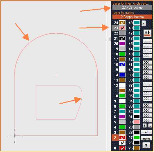
(Image 1: The "outer" outline with an arc, a breakout with a spline curve, both drawn on layer 23)

The outbreak has a defect in the upper left corner. Good to see with the X-ray mode (key [#]):

2 (Image 2:The polyline of the breakout is defective, top left, easily to be seen in the x-ray view

The x-ray view can be cancelled by another #-strike. After the corner of the breakout is closed (the vertical line should snap to the end of the horizontal line) the 3D view of your board should look like this:

3 (Image 3: Result displayed by item "3D view" in menu "View")